
Expansion joints in buildings
What an expansion joint in a building does, where a building needs one, how wide it has to be, what the IS codes say, and the systems that cover it. Written for the engineers and architects who have to put one on a drawing.
A planned gap that decides where the building moves
A concrete frame never stops moving. An expansion joint in a building is a full-depth break in the structure, placed so that the movement happens at a line someone chose, rather than as a crack wherever the frame is weakest. The cover on top keeps the floor, wall or roof usable across the gap.
Four things move a frame, and they do not all move it the same way:
- Temperature. Reinforced concrete grows and shrinks by about 10 × 10−6 of its length per °C. It cycles every day and every season, so the joint opens and closes for the life of the building.
- Drying shrinkage. Concrete shortens as it dries, by a strain of the order of 0.0003 over its life. That movement goes one way only and does not come back, and most of it happens in the first year.
- Settlement. A tower and the podium beside it press on the ground differently and settle at different rates. The line between them has to let one drop relative to the other.
- Earthquake and wind. Two blocks sway out of phase. Where they are too close they hit each other, which is why the seismic code sets a minimum separation.
The structural engineer decides where the gaps go and how wide they are. The joint system is chosen to suit that gap: its movement, the traffic that crosses it, the finish around it and whether water must stay out. How the joint and its cover came to be designed this way is a longer story.
Where a building needs an expansion joint
Length is the reason everyone knows. It is rarely the only one, and on many Indian buildings it is not the one that decides.
Long continuous frames
Indian practice puts a joint in a reinforced concrete frame about every 45 m. Treat that as a default to check, not a rule: an exposed deck wants them closer, a shaded internal frame can go further. How far apart they should be.
L, T and U plans
The arms of an L move in different directions, and the re-entrant corner is where they meet. A plan can be short on every arm and still need a joint at the corner.
Tower beside podium
Different weights, stiffness and foundation pressures mean different settlement and different sway. The line between them is a separation, whatever the length.
A change of foundation or structure
Raft to piles, frame to load-bearing walls, a steel roof on a concrete frame: wherever the structure changes how it carries load, it will move differently on each side.
Between two buildings
A new block against an existing one, or two phases built years apart, cannot share a frame. They need a full separation and a cover that bridges it.
Paired columns and beams
The joint runs through the whole frame, so each side carries its own columns and beams at the joint line. Plan for the doubled columns early; they are hard to add later.
Once the structural joint is fixed, it runs through every floor, wall, ceiling, roof and façade it crosses. Each of those crossings needs its own cover system, which is why one building joint usually turns into several joint types on the schedule.
How wide the gap has to be
The gap is set by the larger of two cases: the thermal and shrinkage movement of the blocks on each side, and, where the seismic code applies, the separation the blocks need so that they do not collide.
Thermal movement of one bay = α × L × ΔT
For a 45 m bay in Delhi NCR, with α = 10 × 10−6 per °C and an effective range of 45 K:
10 × 10−6 × 45,000 mm × 45 = about 20 mm of opening and closing.
The same bay in Chennai, at about 20 K, moves about 9 mm. Shrinkage adds a one-way closing of the order of 13 mm over 45 m, much of it before the joint is fitted.
The seismic case is usually far larger. For two 15-storey blocks in Zone IV, each with a calculated roof displacement of about 40 mm and a response reduction factor R of 5, the separation works out at 5 × (40 + 40) = 400 mm. That is an order of magnitude more than the thermal figure, and a different class of joint: a seismic system such as the SeismAtec 450, rated for gaps up to 500 mm.
The step-by-step method, with a table for each Indian climate, is in expansion joint width: how to calculate the gap. The movement calculator runs the thermal arithmetic for your bay and city, and what the seismic zone changes works through the separation.
What the joint looks like in the slab
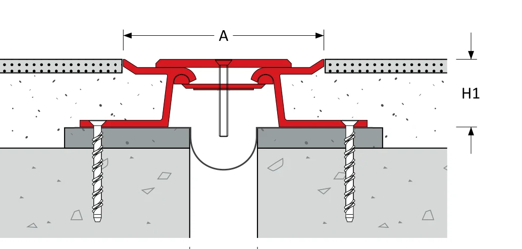
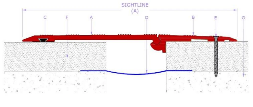
A floor joint is more than a plate over a gap. An aluminium frame sits in a recess, the blockout, along each slab edge, bedded and anchored into the concrete. A cover plate bridges the gap and stays centred as it opens and closes. Beneath it, a membrane lapped onto the waterproofing on each side keeps water out of the floor below.
Two consequences matter at design stage. The blockout is several times wider than the gap, so it has to be on the structural drawings before the pour. And the frame height has to match the finish build-up, or the joint ends up proud of the floor or sunk below it. Blockout, rebate and fixing sets out what the slab has to leave.
The types of expansion joint in a building, briefly
"Type" is used three ways: where the joint sits, what movement it takes and what covers it. The three answers together name the system.
| Where it sits | What it usually takes | What we make in India for it |
|---|---|---|
| Floor to floor | Thermal, shrinkage, people and trolleys, sometimes cars | MegAtec 300, 310, 340, 370; FlexAtec 1200 where a seal suits |
| Floor to wall | The same, against a vertical face | The A02 corner version of each floor system |
| Wall to wall, corner and ceiling | Movement without traffic | MegAtec 360 |
| Roof to roof, roof to wall | Movement and weather | MegAtec 610 |
| Seismic separation | Large movement in several directions | SeismAtec 450 |
A fire barrier inside the joint is available on request, its rating confirmed per job, wherever a joint crosses a fire compartment line. The full breakdown, with gap ranges, is in types of expansion joints in buildings; metal cover or seal covers the choice between the two kinds of cover.
What the IS codes say about expansion joints
Plain and reinforced concrete
Deals with expansion joints in clause 27: where a structure’s plan changes abruptly, and in long structures. Practice has settled on about 45 m. It refers the design of the joint itself on to IS 3414.
Joints in buildings
The code of practice for the design and installation of joints in buildings. Where IS 456 says a joint is needed, IS 3414 is the document it points to for how the joint is made.
Earthquake-resistant design
Part 1 sets the separation between adjacent blocks from their calculated displacements, multiplied by the response reduction factor R. In Zones IV and V it usually decides the width.
None of the three specifies the cover: its movement class, its load, its fixing or its membrane. That has to be written into the specification. Expansion joints as per the IS codes goes through each code, and what to write where it is silent.
Putting the joint into the drawings and the tender
- A joint scheduleEvery joint located, with its gap, its calculated movement, the traffic over it and the system and blockout for it. We prepare one from GFC or concept drawings at no cost: get a joint schedule.
- A performance clauseWrite what the joint must do (movement, ASTM E-1399 cycling, traffic, membrane, fire barrier where needed), not only a product name, so a substitute has to match the performance. Expansion joint details and specification has the clause and the section drawings.
- The tender lineGovernment and PSU tenders use CPWD DSR items 5.44, 5.45 and 5.46 for floor, wall and roof joints. The DSR items shows what each asks for and what it leaves out.
Pricing, supply and repair questions are answered in the FAQ. At submittal, ask for the data sheet of the exact joint, the cross-section for each location, the method statement and the name of whoever will install it. What a method statement for expansion joint installation should cover.
How expansion joints fail, and what treatment involves
Most joints that fail were never sized for the movement they see, were fixed into a poor slab edge, or had their membrane lap left to nobody.
- Noise. A plate that clacks under traffic has lost its fixing or its bedding.
- Lift and trip. A frame proud of the floor, or a plate that has walked along the line.
- A crack in the finish alongside. The joint is not moving freely, so the finish moves instead.
- Water below. A stain, a drip or efflorescence under the line: the membrane, almost always.
The five signs explains what each one means. Putting it right, in the sense contractors and facility managers use the word expansion joint treatment, runs survey, movement check, slab-edge repair and a new system, in that order.
The expansion joint systems we make in India
Eight systems are made at our New Delhi works and installed by our own crews. Each card leads to the system’s data sheet, section drawing and specification clause.
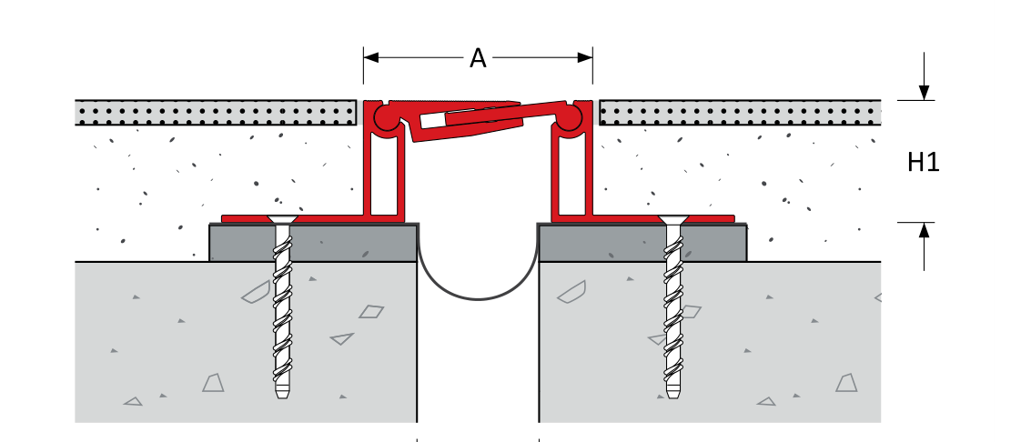 MegAtec 300Foot and light traffic, ADA-compliant surfaceMade in IndiaFloor
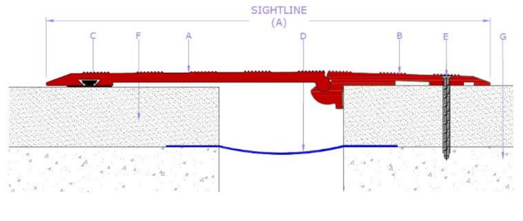 MegAtec 310Floor and floor-to-wall, no visible fixings, gaps 50–250 mmMade in IndiaFloor
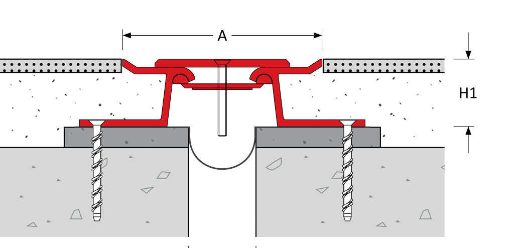 MegAtec 340Hairline serrated slip-resistant surface, ADA compliantMade in IndiaFloor
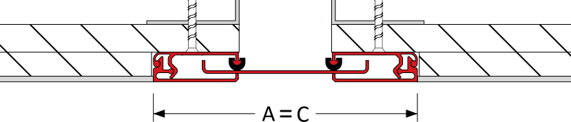 MegAtec 360Wall, corner and ceiling, gaps 25–200 mmMade in IndiaWallCeiling
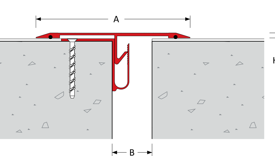 MegAtec 370Slip-resistant floor joint, gaps 25–150 mmMade in IndiaFloor
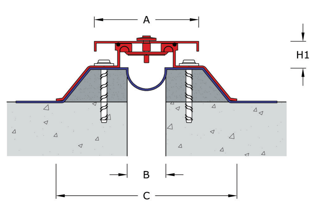 MegAtec 610External centre-plate roof joint, gaps 25–300 mmMade in IndiaRoof
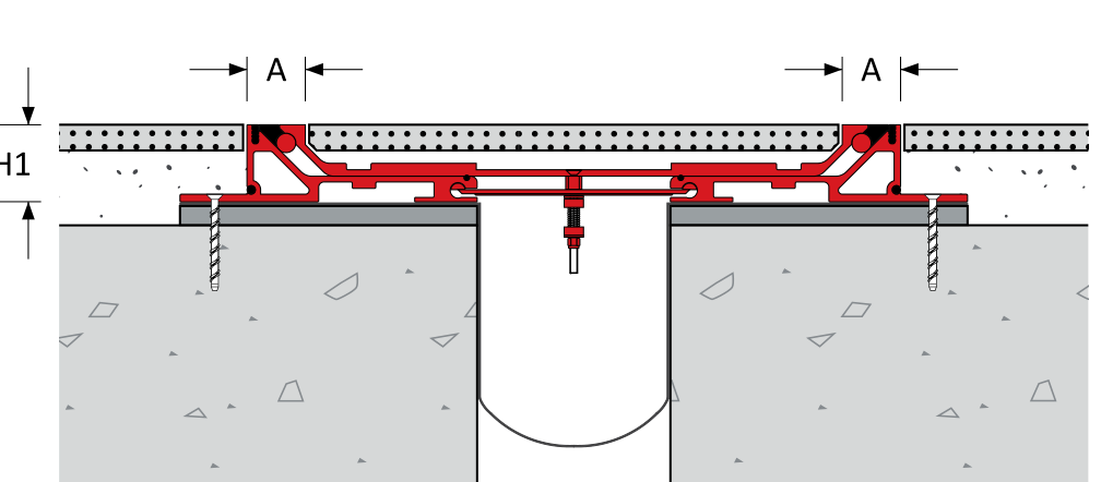 SeismAtec 450Central-pan seismic floor joint, gaps 50–500 mmMade in IndiaFloorSeismic
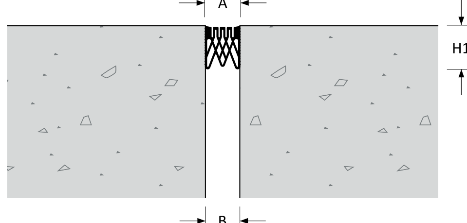 FlexAtec 1200Ribbed seal, ADA-compliant, gaps 25–75 mmMade in IndiaFloorWall
Three buildings, three different reasons for the joint

Have the drawings? Send them.
At design stage we return a joint schedule; at tender stage we name the system against each BOQ line and quote to supply and install.